Tableau Number 2
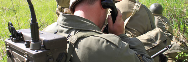
The SCR300 Radioman
Date: April 2013
Author: Pat Costa - 88th ID & 5th Rangers Dog Company
90th IDPG Editors - Chris Guska, Lee Mudd, Mike Ellis
Notes from the manuals on equipment:
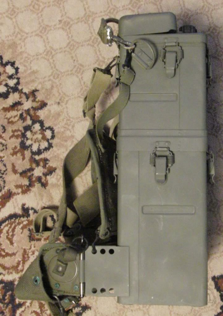
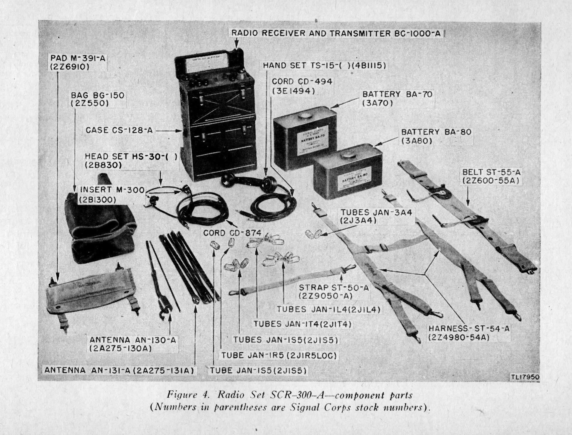
SCR-300 Components & Accessories Top Unit Radio BC-1000 Strap ST-50-A Harness ST-54-A Bottom Unit Case CS-128 Belt ST-55-A (Inside Bottom Unit) Battery BA-70 Battery BA-80 Accessories Bag BG-150 Antenna AN-130 Antenna AN-131 Handset TS-15 Microphone T-45 Auxiliary Accessories Bag BG-187 Antenna RC-291
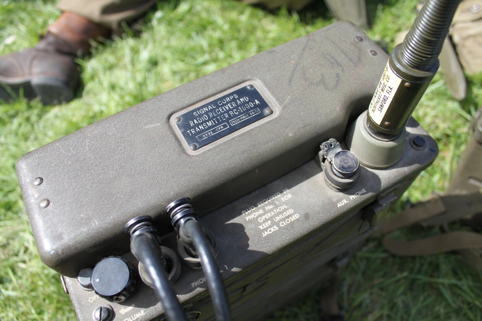
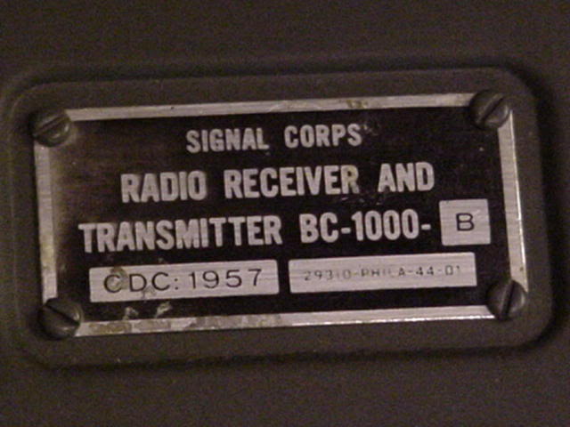
The SCR-300 has two different nomenclature variants. The more common type is the SCR-300-A with the BC-1000-A. Normally, this type of radio is just shorthanded to SCR-300. The other type is SCR-300-B with the BC-1000-B.
(TM 11-242, March 1946, TO 16-40, SCR 300-5, C1. Pg 1
(TM 11-4024, Radio Receiver and Transmitters BC-1000-A and –B Repair Instructions, August 1945. Pg 5)
Usually, the data plate is a dead give away as to which SCR-300 it is.
SCR-300 Latch Springs:
A note on the SCR-300 latch springs to be mentioned. It appears from the pictures that latches that have springs are historically incorrect as none of the pictures shown have such latch springs.Furthermore, Modification Work Order 11-242-2 dated 14 June 1951 specified the change from the oval shaped latch springs to the coil spring type.
Provided is a comprehensive list of the accessories along with a brief explanation of each and an accompanying italicized quoted description from TM 11-242, Radio Set SCR-300-A, Feb. 1945 where applicable.
The accessories for the radio were typically sourced from the division signal company
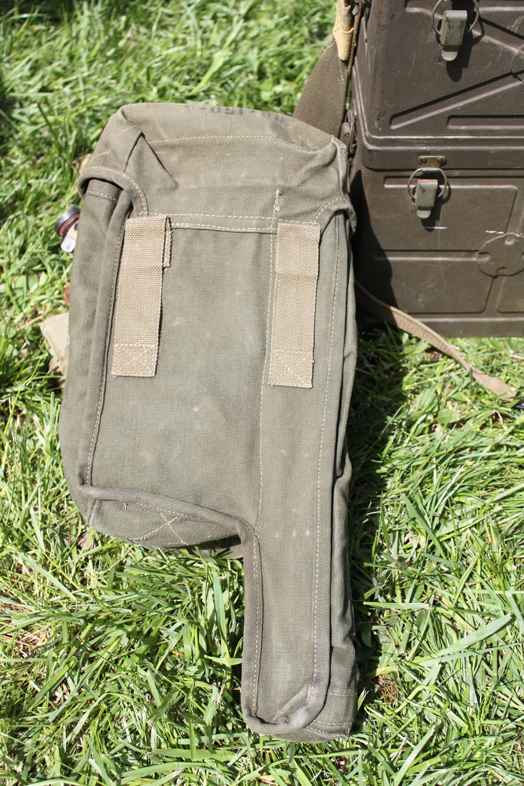
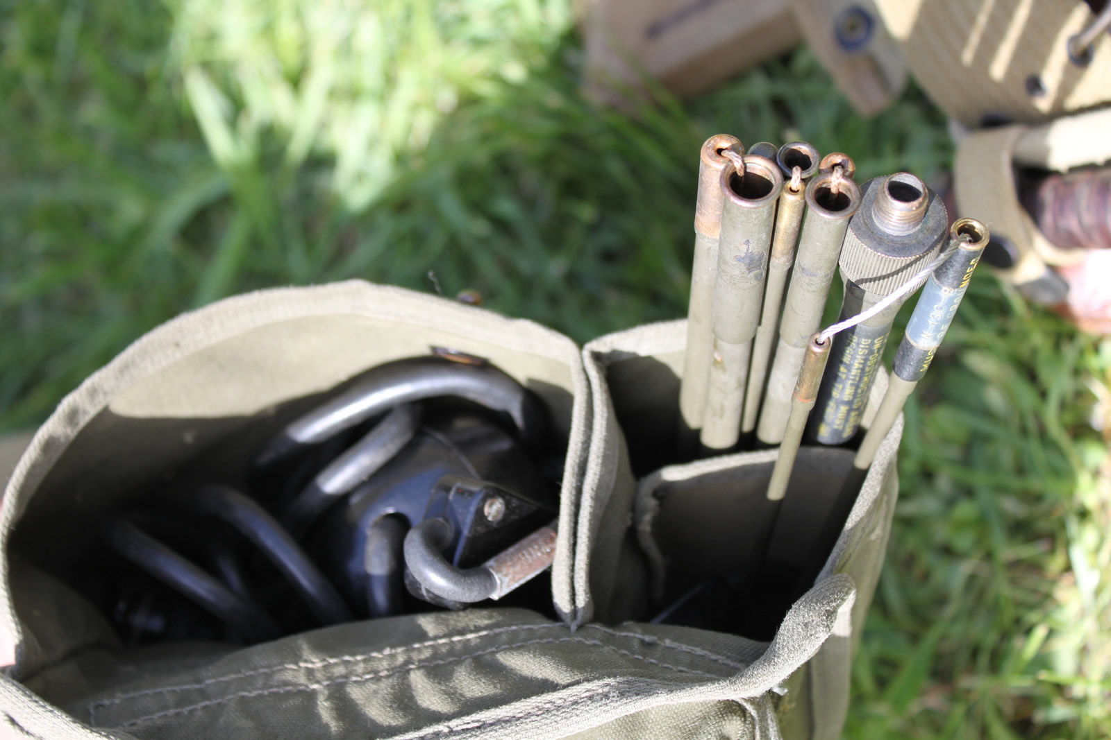
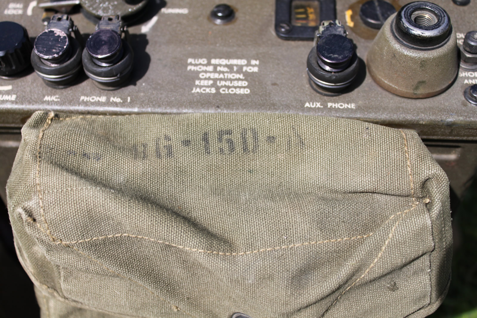
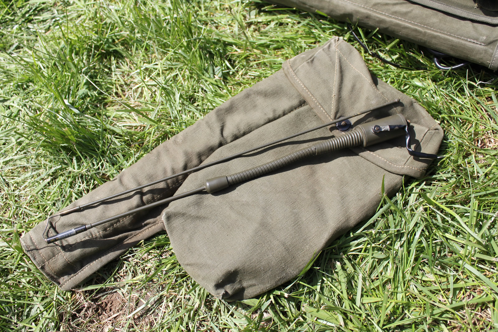
This is a canvas bag consisting of three compartments; the first for storing Antenna AN-130-A, the second for storing Antenna AN-131-A, and the third for storing Handset TS-15 and Headset HS-30.
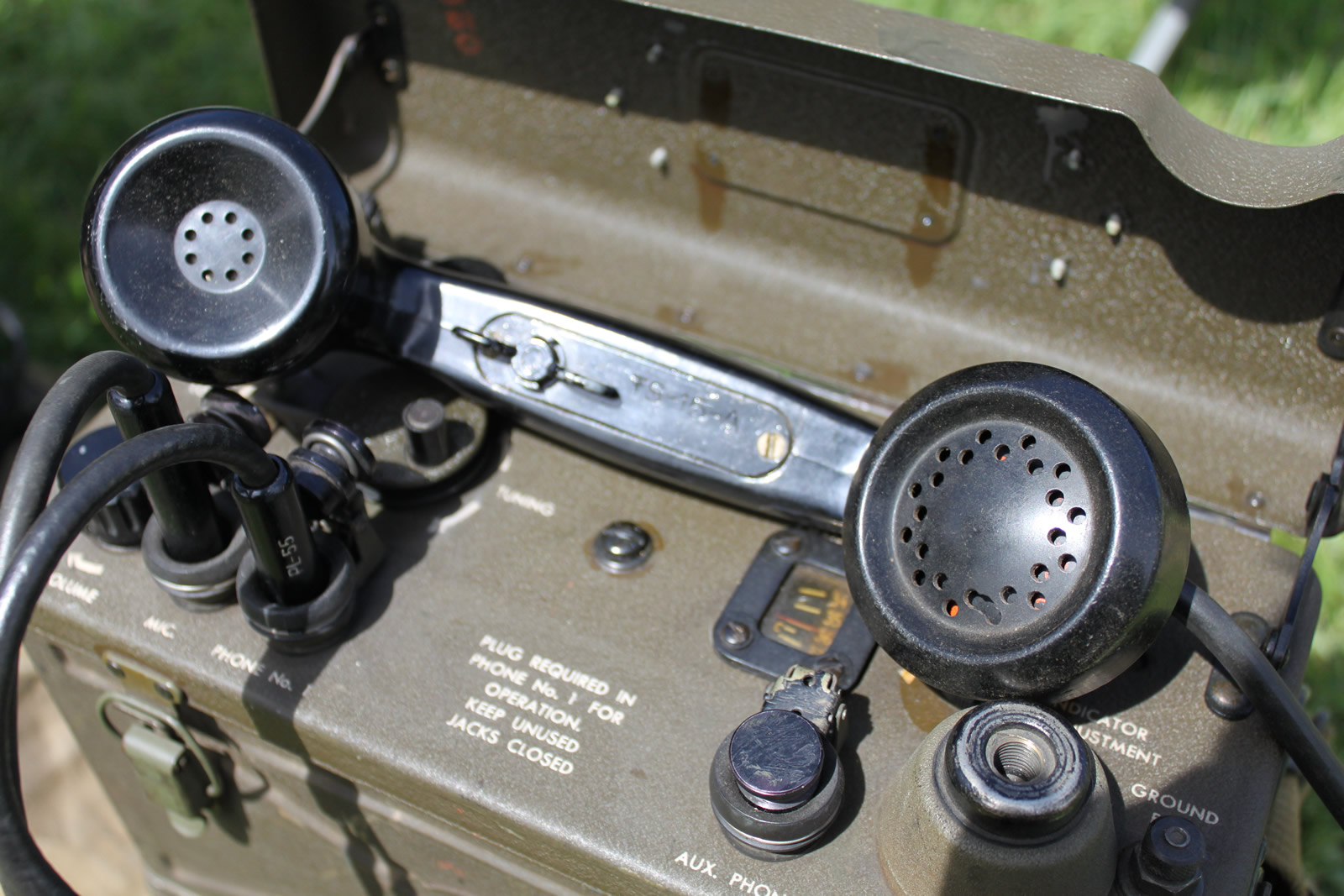
Handset TS-15 with Cord CD-494 terminates in Plug PL-55 (receiver unit) and Plug PL-68 (microphone). A receive-transmit switch is incorporated in the handle. The Receiver unit of Handset TS-15 has an impedence of 250 ohms.
Modification Work Order SIG 25 changed most of the TS-15 A & C handsets to HS-23/U in February, 1945
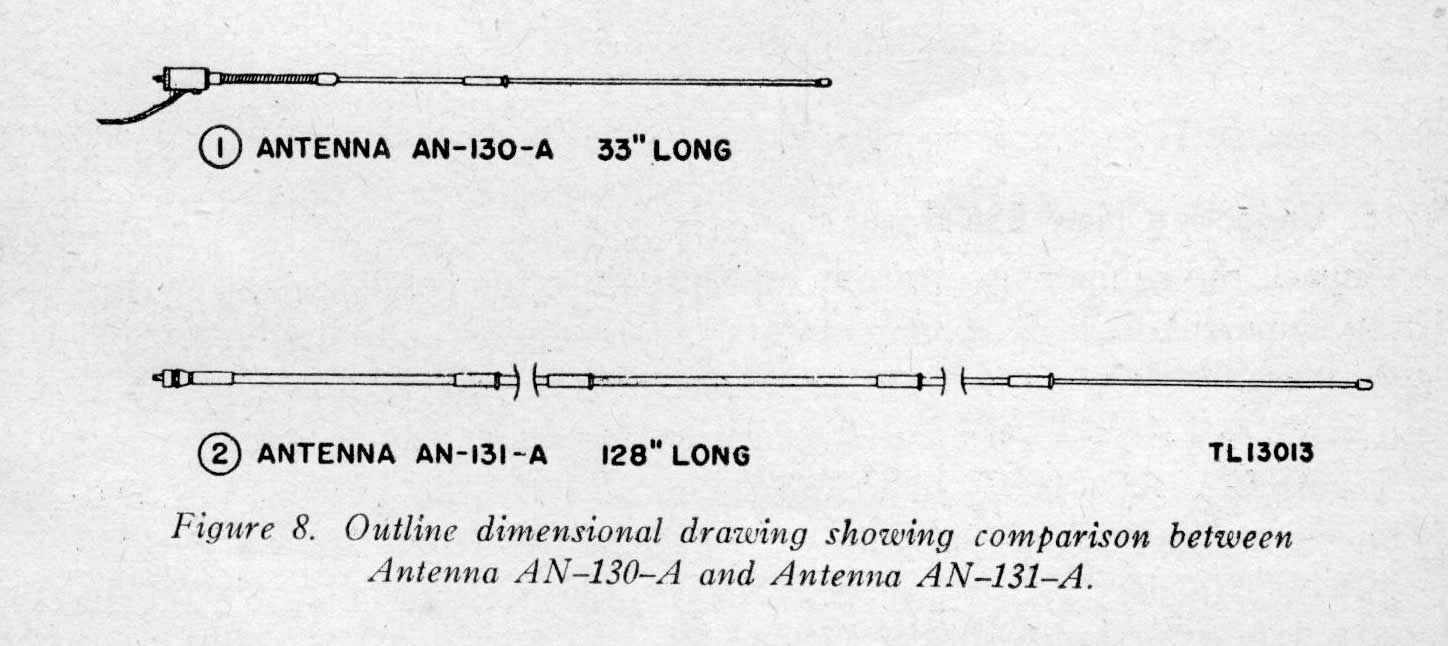
Antenna AN-130-A is a two section unit which is 33 inches long when assembled. The sections are held together by a kinkless, stainless steel cable which eliminates the possibility of losing a section and permits rapid assembly of the antenna. The bakelite case at the base of the antenna houses an antenna-matching circuit which consists of a loading coil and capacitor. The flexible lead with a spade lug, attached to the bakelite shell, must be connected to the binding post marked GROUND FOR SHORT ANT. of Radio Reciever and Transmitter BC-1000-A. This connection is necessary to complete the antenna-matching circuit. A threaded stud is provided at the base of the antenna to attach it to the antenna terminal of the set. A flexible section near the base of the antenna allows the antenna to be bent at an angle so that it can always be adjusted to a vertical position. When not in use, Antenna AN-130-A is carried in Bag BG-150-A
Antenna AN-131-A is a lightweight, tapered, flexible, eight-section antenna which is 10 feet, 8 inches long when assembled. The eight sections are held together by a kinkless, stainless steel cable which runs through the entire length of the antenna and which is under spring tension. This cable not only permits rapid assembly but also eliminates any possibility of losing a section. A threaded stud is provided at the base of the antenna to attach the antenna to the antenna terminal of the set. The GROUND FOR SHORT ANT. binding post is not used with antenna AN-131-A since no antenna-matching circuit is required for this antenna. Antenna AN-131-A is designed for use in unobstructed areas only. When not in use, Antenna AN-131-A is carried in BAG BG-150-A
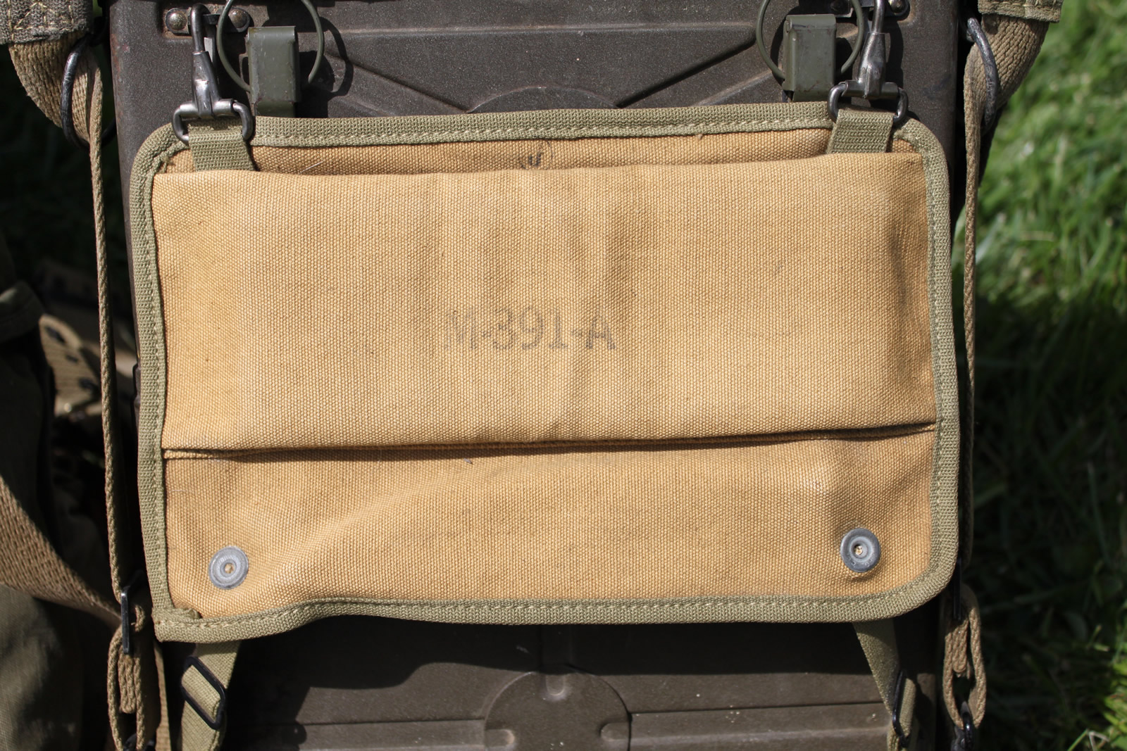
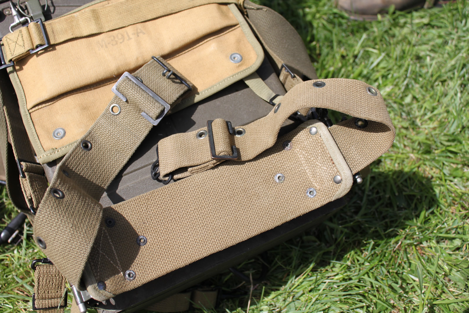
Harness ST-54-A, Belt ST-55-A and Pad M-391-A, when attached to Radio Set SCR-300 and Case CS-128, provide a means for carrying the set during portable operation.
Used to support the back/prevent chaffing when used with the harness
Attached to case CS-128 by pins, the belt securely fastenes the radio to the wearer. It is also possible to wrap the belt around the battery box to get it out of the way, yet still provide kidney height padding.
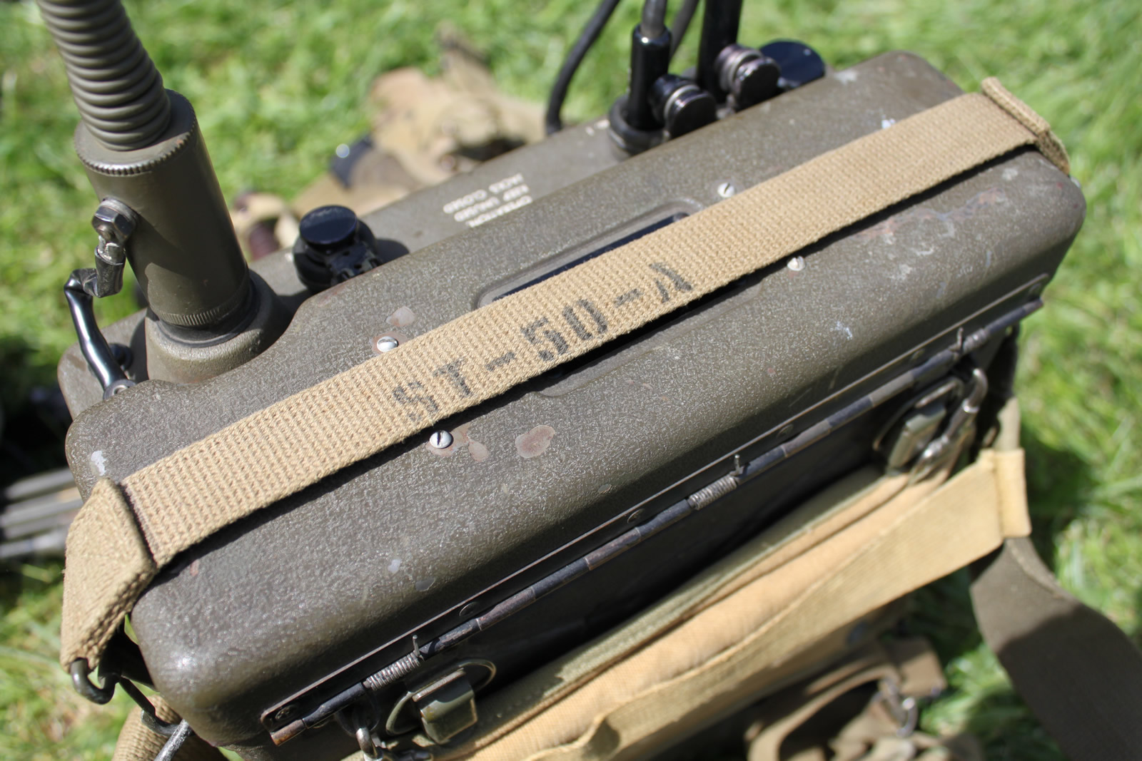
Strap ST-50-A is issued to facilitate lifting or carrying the set by hand.
Power is obtained from a single battery secured to the bottom fo the set. This battery may be either Battery BA-70 which gives 20-25 hours of service ...
These figures only apply in moderate climates. Each battery consists of three dry battery sections of 4.5 volts, 60 volts, and 90 volts respectively. The first section supplies the necessary voltage to the microphone circuit and to the filaments of the radio reciever and transmitter. The second and third sections, connected in series supply 150 volts to the plate circuit of the transmitter. The third section supplies 90 volts to the receiver plate circuits. The battery is electrically connected to the radio chassis by a flexible rubber-covered cord and plug assemblyand is fastened with web straps.
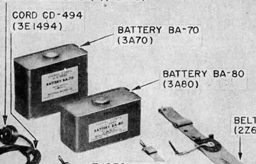
Power is obtained from a single battery secured to the bottom fo the set... Battery BA-80 which gives 12-14 hours of service.
As has been mentioned, Battery BA-80 is similar to Battery BA-70, differing only in physical size and current capacity. Battery BA-80 is used when extreme portability and lightness of weight are necessary.
SCR-300 Auxiliary Equipment:
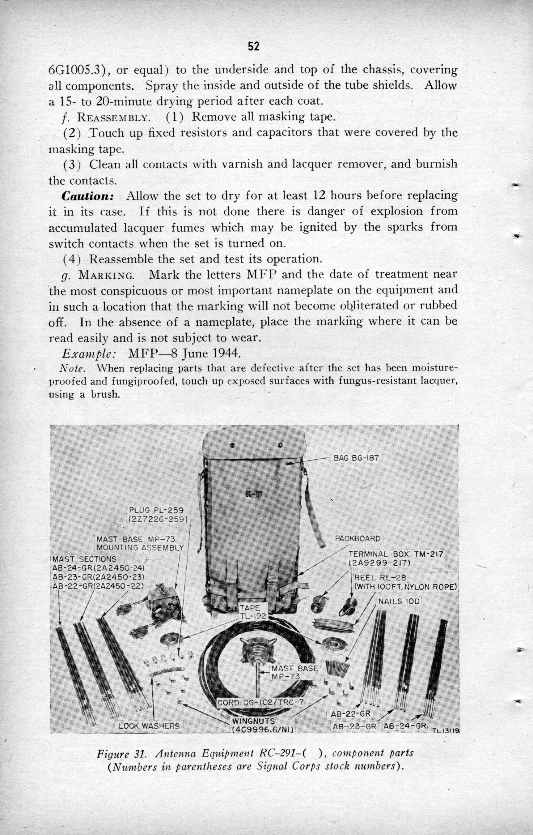
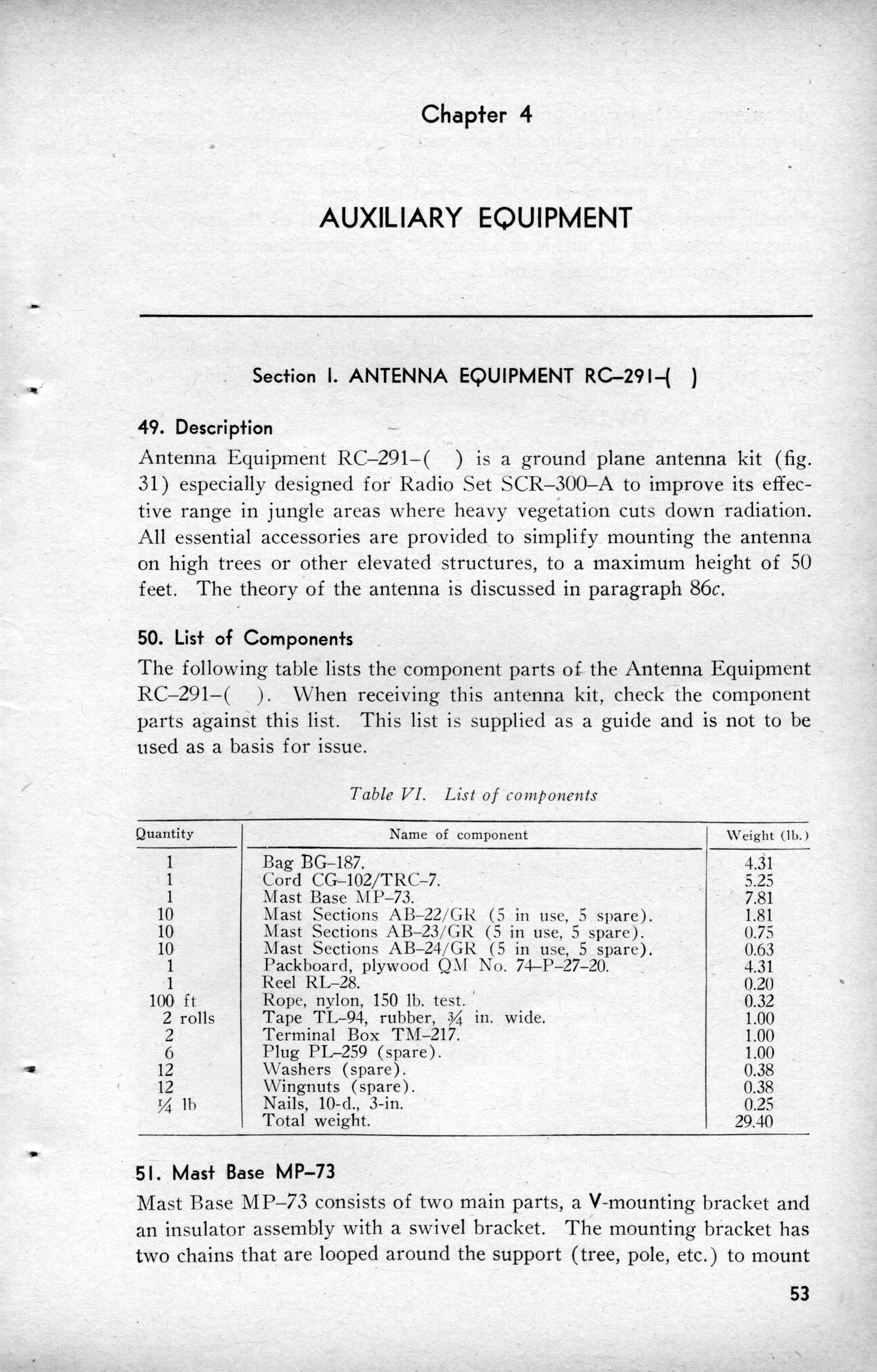
Used to mount the antenna in areas with much overhead brush such as in a jungle
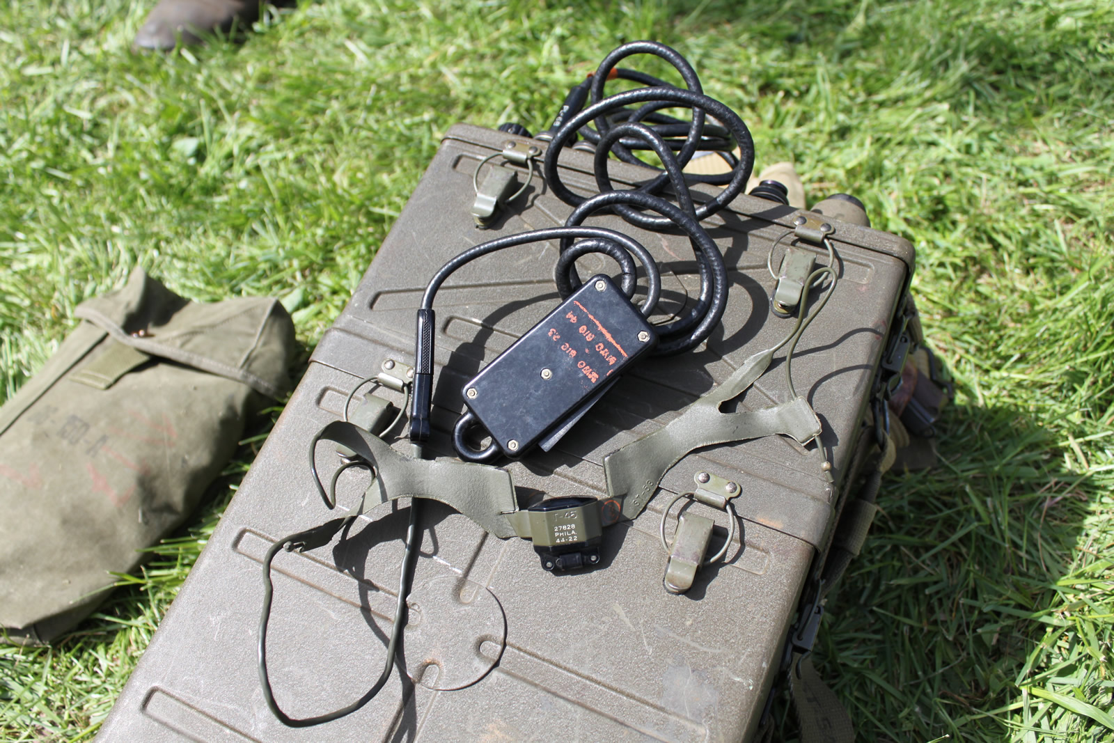
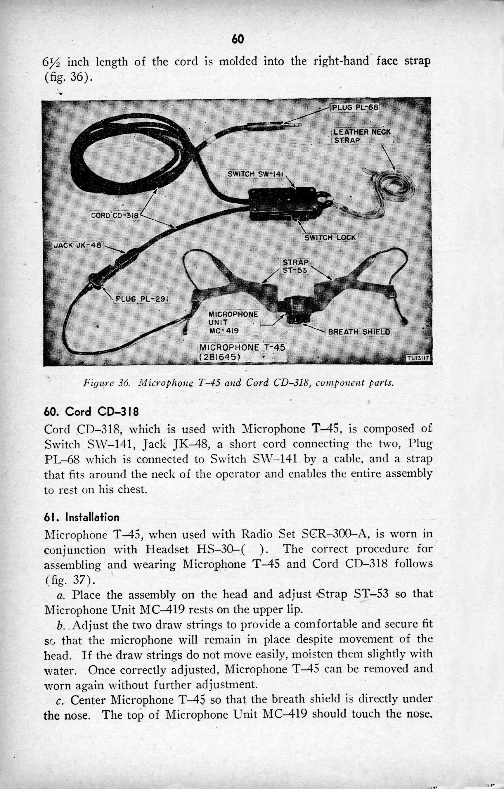
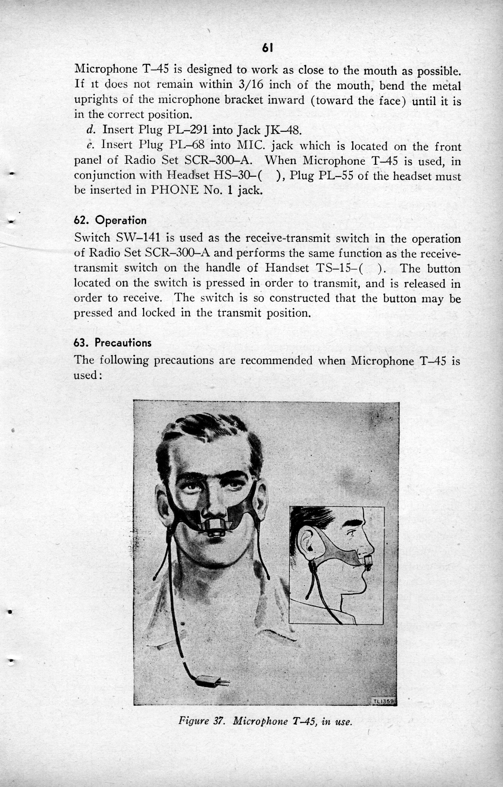
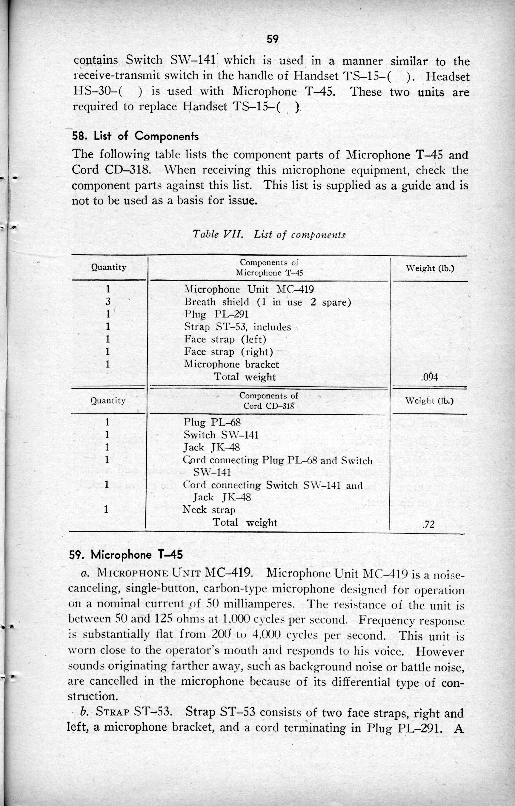
Microphone T-45 & Cord CD-318:
A microphone used when the operator must have both hands free
Cord used to connect the microphone to the radio.
Carrying Methods:
With all the equipment listed, soldiers when using the SCR-300 had three types of carrying methods.
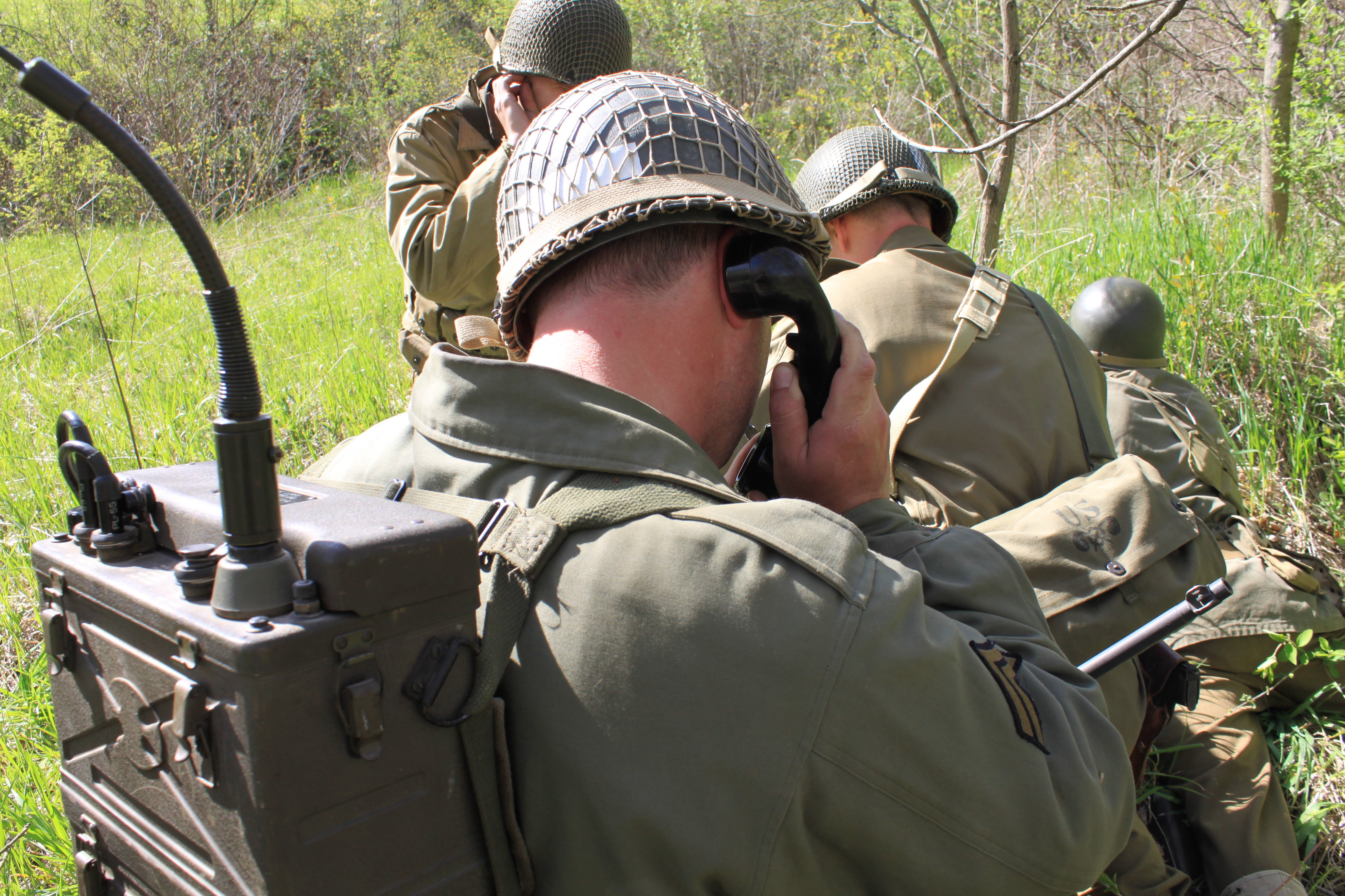
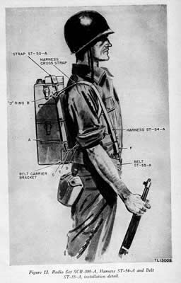
Harness Method:
The carrying harness was configured as illustrated below with the thin straps of the ST-54 harness passed through the D-rings and connected to the belt carrier bracket. The forward hooks of the ST-54 harness connected to the eyelets on the ST-55 belt, or extended back and connected to the belt carrier bracket allowing the omission of the ST-55 belt.
This is the most commonly seen method.
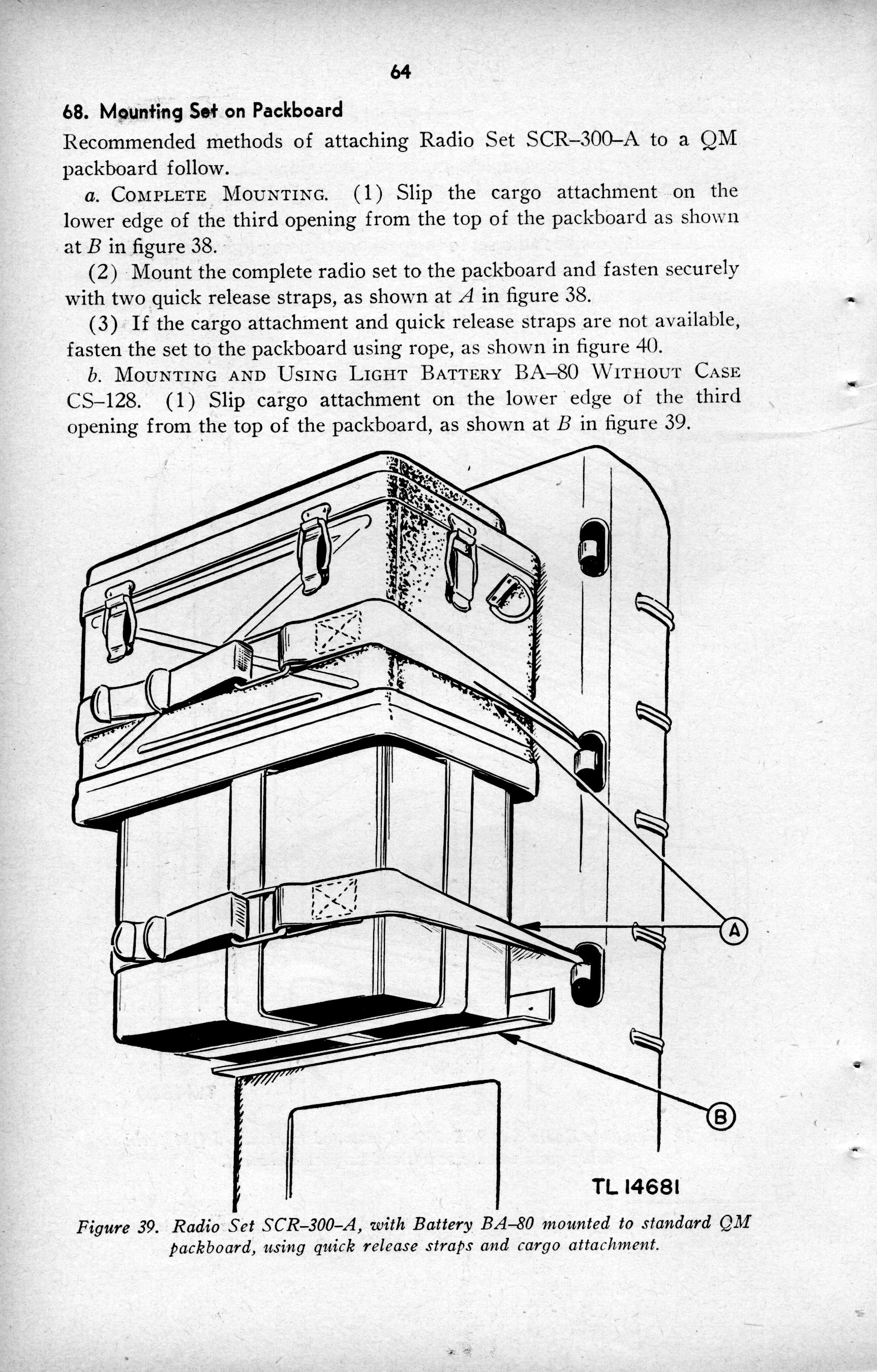
Packboard Method:
One method involved a securing the radio to a packboard with or without the battery case using quick release straps and/or rope
This is occasionally seen.
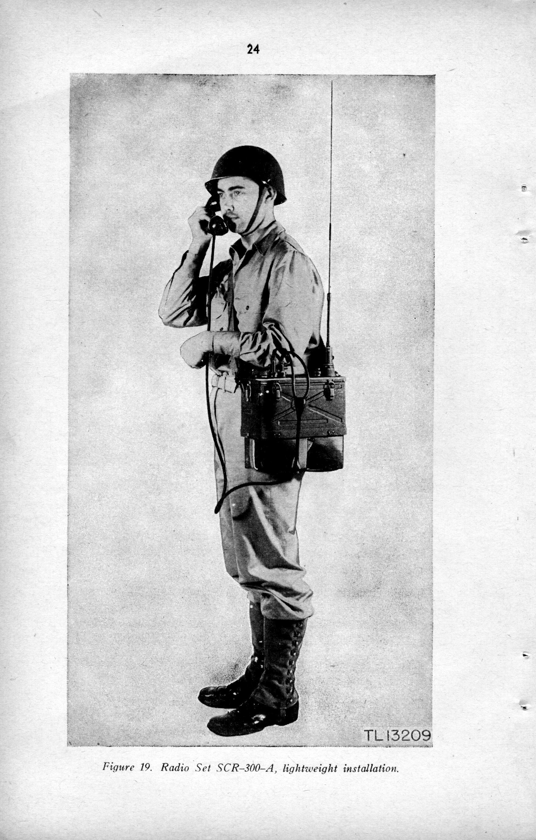
"20lb Man Purse" Method:
Another method was to install the light weight battery without the battery case and use the Strap-ST-50-A to carry the radio.The author has never observed this method in use outside of manuals.
On to Section 3: Original Photographs - Key Observations
Introduction
Section 1: By the book - TO&E
Section 2: Notes from the manuals on equipment (you are here)
Section 3: Original Photographs - Key Observations
Section 4: Notes on Training and Use
Section 5: Putting it together- Modern Interpretation
Section 6: Adapting the SCR300 for Reenactment Use